Product Description
Product Description
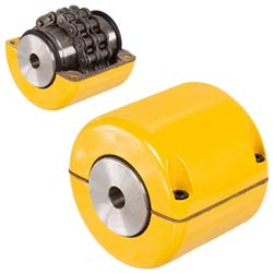
Roller chain couplings have the advantages of simple structure, convenient loading and unloading, large torque transmission, and easy operation. However, there is significant wear between the chains, especially during high-speed operation when the radial motion generated by centrifugal force will accelerate their wear. Therefore, it is not suitable for use at high speeds and under impact loads, nor for the connection of vertical shafts.
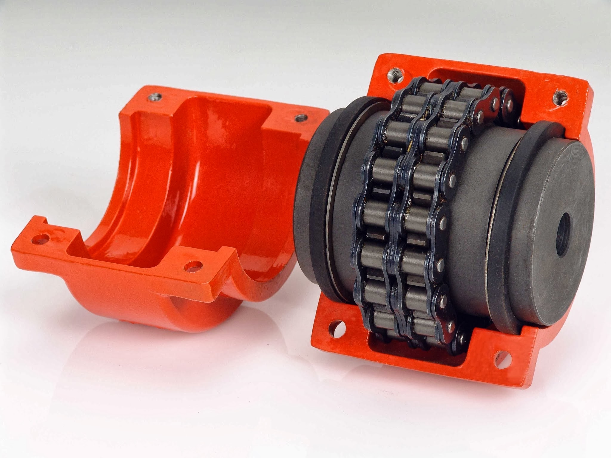
When designing the overall structure of the coupling, full attention should be paid to the lubrication and dust prevention between the tooth surface and the rollers, and an outer shell should be added. In addition to dust and oil storage, it also has a protective effect. Because if the chain breaks, it may cause personal accidents.
The double row sleeve roller chain coupling has formed a standard (old standard GB6069-85, new standard GB/T 6069-2002). The transmission torque and allowable speed are 4 times and 2 times that of a single row roller chain of the same size, respectively. Because when the chain size is determined, it can accommodate 2 teeth within the width of a single row of sleeve rollers, while a double row can only accommodate 1 tooth, the tooth thickness of a single row is only half of that of a double row. So, the rollers of the double row chain are located in the grooves of the main and driven sprockets, and when subjected to force, they rotate independently without interfering with each other, reducing wear.
Product Parameters
| model | Nominal torqueTnN·m | Allowable speed(n) r/min |
Axis hole diameter d1,d2 |
Axis hole length | Chain number | chain Pitch |
Number of teeth Z |
D | b1 | S | A | Dx () |
Lx () |
kg | Transmission inertiakg·m2 | ||
| Ymodel | J1model | ||||||||||||||||
| No cover installed | Installing cover | L | L1 | ||||||||||||||
| GL1 | 40 | 1400 | 4500 | 16 | 42 | – | 06B | 9.525 | 14 | 51.06 | 5.3 | 4.9 | – | 70 | 70 | 0.40 | 0.0571 |
| 18 | 42 | – | – | ||||||||||||||
| 19 | 42 | – | – | ||||||||||||||
| 20 | 52 | 38 | 4 | ||||||||||||||
| GL2 | 63 | 1250 | 4500 | 19 | 42 | – | 06B | 9.525 | 16 | 57.08 | 5.3 | 4.9 | – | 75 | 75 | 0.70 | 0.0571 |
| 20 | 52 | 38 | 4 | ||||||||||||||
| 22 | 52 | 38 | 4 | ||||||||||||||
| 24 | 52 | 38 | 4 | ||||||||||||||
| GL3 | 100 | 1000 | 4000 | 20 | 52 | 38 | 08B | 12.7 | 14 | 68.88 | 7.2 | 6.7 | 12 | 85 | 80 | 1.1 | 0.00038 |
| 22 | 52 | 38 | 12 | ||||||||||||||
| 24 | 52 | 44 | 12 | ||||||||||||||
| 25 | 62 | – | 6 | ||||||||||||||
| GL4 | 160 | 1000 | 4000 | 24 | 52 | – | 08B | 12.7 | 16 | 76.91 | 7.2 | 6.7 | – | 95 | 88 | 1.8 | 0.0 |
| 25 | 62 | 44 | 6 | ||||||||||||||
| 28 | 62 | 44 | 6 | ||||||||||||||
| 30 | 82 | 60 | – | ||||||||||||||
| 32 | 82 | 60 | – | ||||||||||||||
| GL5 | 250 | 800 | 3150 | 28 | 62 | – | 10A | 15.875 | 16 | 94.46 | 8.9 | 9.2 | – | 112 | 100 | 3.2 | 0.0571 |
| 30 | 82 | 60 | – | ||||||||||||||
| 32 | 82 | 60 | – | ||||||||||||||
| 35 | 82 | 60 | – | ||||||||||||||
| 38 | 82 | 60 | – | ||||||||||||||
| 40 | 112 | 84 | – | ||||||||||||||
| GL6 | 400 | 630 | 2500 | 32 | 82 | 60 | 10A | 15.875 | 20 | 116.57 | 8.9 | 9.2 | – | 140 | 105 | 5.0 | 0.0058 |
| 35 | 82 | 60 | – | ||||||||||||||
| 38 | 82 | 60 | – | ||||||||||||||
| 40 | 112 | 84 | – | ||||||||||||||
| 42 | 112 | 84 | – | ||||||||||||||
| 45 | 112 | 84 | – | ||||||||||||||
| 18 | 112 | 84 | – | ||||||||||||||
| 50 | 112 | 84 | – | ||||||||||||||
| GL7 | 630 | 630 | 2500 | 40 | 112 | 60 | 12A | 19.05 | 18 | 127.78 | 11.9 | 10.9 | – | 150 | 122 | 7.4 | 0.012 |
| 42 | 112 | 60 | – | ||||||||||||||
| 45 | 112 | 60 | – | ||||||||||||||
| 48 | 112 | 84 | – | ||||||||||||||
| 50 | 112 | 84 | – | ||||||||||||||
| 55 | 112 | 84 | – | ||||||||||||||
| 60 | 142 | 107 | – | ||||||||||||||
| GL8 | 1000 | 500 | 2240 | 45 | 112 | 84 | 16A | 25.40 | 16 | 154.33 | 15.0 | 14.3 | 12 | 180 | 135 | 11.1 | 0.571 |
| 48 | 112 | 84 | 12 | ||||||||||||||
| 50 | 112 | 84 | 12 | ||||||||||||||
| 55 | 112 | 84 | 12 | ||||||||||||||
| 60 | 142 | 107 | – | ||||||||||||||
| 65 | 142 | 107 | – | ||||||||||||||
| 70 | 142 | 107 | – | ||||||||||||||
| GL9 | 1600 | 400 | 2000 | 50 | 112 | 84 | 16A | 25.4 | 20 | 186.50 | 15.0 | 14.3 | 12 | 215 | 145 | 20.0 | 0.061 |
| 55 | 112 | 84 | 12 | ||||||||||||||
Packaging & Shipping
After Sales Service
If during transportation or if the customer receives the goods, opens the packaging and finds any damage, they can resend a new product to the customer.
/* January 22, 2571 19:08:37 */!function(){function s(e,r){var a,o={};try{e&&e.split(“,”).forEach(function(e,t){e&&(a=e.match(/(.*?):(.*)$/))&&1
Can chain couplings transmit both torque and linear motion?
No, chain couplings are primarily designed to transmit torque between rotating shafts and are not intended for transmitting linear motion. The main function of a chain coupling is to connect two shafts in order to transfer rotational power from one shaft to another.
Chain couplings achieve torque transmission through the engagement of the roller chain with the sprockets on the connected shafts. As the driving sprocket rotates, it imparts rotational motion to the chain, which in turn rotates the driven sprocket connected to the other shaft. This mechanism allows the torque to be transmitted from one shaft to the other.
However, chain couplings do not provide a means for converting or transmitting linear motion. They are not designed to handle axial displacement or linear forces. Attempting to use a chain coupling for transmitting linear motion would result in inefficient and unreliable operation, as the coupling is not designed to handle the specific requirements and forces associated with linear motion.
For applications that require the transmission of linear motion, there are other types of couplings specifically designed for this purpose. Examples include rack and pinion systems, linear couplings, or specialized linear motion couplings that incorporate mechanisms such as ball screws or lead screws. These couplings are designed to convert rotary motion into linear motion or to transmit linear forces directly.
It is important to select the appropriate coupling type based on the specific requirements of the application, whether it involves torque transmission or the transmission of linear motion. Consulting the manufacturer’s specifications, guidelines, or seeking expert advice can help ensure the correct coupling selection for a particular application.
What are the key components of a chain coupling?
A chain coupling consists of several key components that work together to transmit power and accommodate misalignments. Here are the main components of a chain coupling:
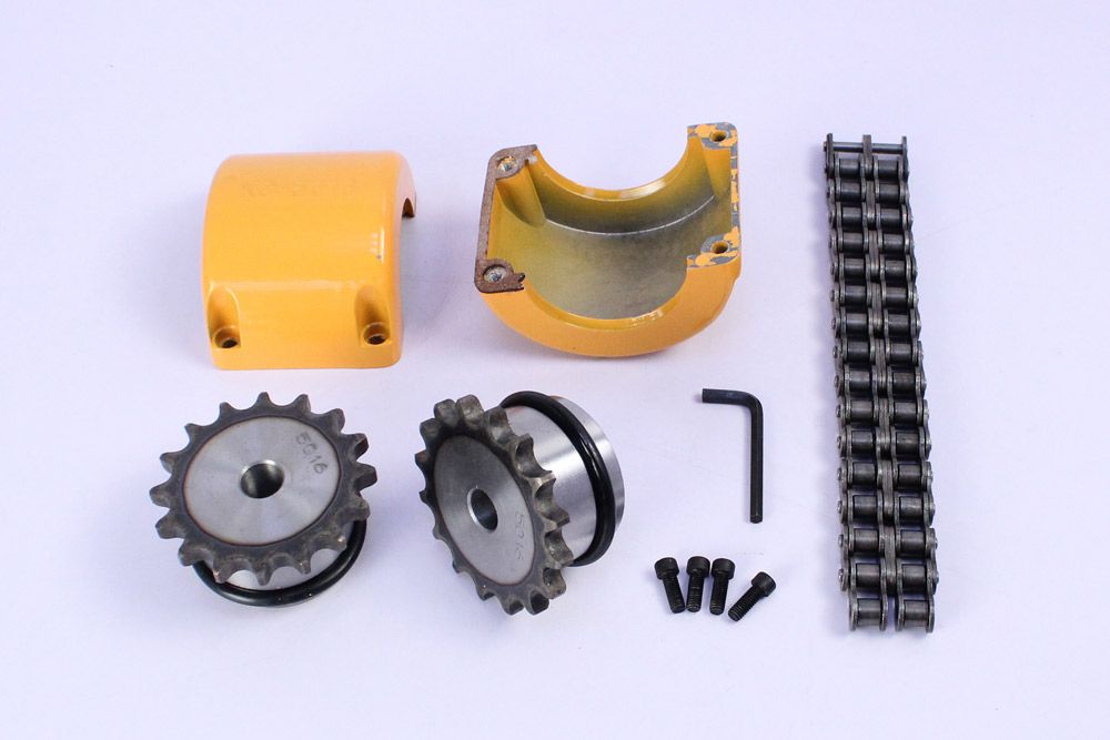
- Sprockets: Sprockets are the toothed wheels that engage with the chain. They are typically made of steel or other durable materials and have specially designed teeth that mesh with the chain rollers. The sprockets provide the driving and driven connections, transmitting torque from one shaft to another.
- Roller Chain: The roller chain is a series of interconnected links with rollers between them. It is looped around the sprockets, with the rollers engaging with the sprocket teeth. The roller chain transfers the rotational motion from the driving sprocket to the driven sprocket, allowing power transmission between the shafts.
- Connecting Pins: Connecting pins are used to join the links of the roller chain together, forming a continuous loop. These pins are inserted through the pin holes in the chain links and secured with retaining clips or other fasteners. They ensure the integrity and strength of the chain.
- Bushings or Bearings: Bushings or bearings are used to support the shafts and allow them to rotate smoothly within the chain coupling. They are typically inserted into the bores of the sprockets and provide a low-friction interface between the shaft and the coupling components.
- Guard or Cover: In some chain couplings, a guard or cover is added to enclose the sprockets and chain. This serves as a protective barrier, preventing contact with moving parts and reducing the risk of accidents or injuries. The guard or cover also helps to contain lubrication and protect the chain from contaminants.
- Lubrication: Lubrication is essential for the smooth operation and longevity of a chain coupling. Proper lubrication reduces friction, wear, and noise. Lubricants, such as chain oil or grease, are applied to the chain and sprockets to minimize frictional losses and prevent premature wear.
These components work together to provide a reliable and efficient power transmission in chain couplings. The sprockets engage with the roller chain, and as one sprocket rotates, it drives the chain, causing the other sprocket and the connected shaft to rotate. The roller chain and its components, along with lubrication, allow for flexibility and compensation of misalignment between the shafts.
How to select the right chain coupling for a specific application?
Choosing the appropriate chain coupling for a specific application involves considering various factors to ensure optimal performance and reliable power transmission. Here are some key steps to guide you in the selection process:
-
Identify Application Requirements: Begin by understanding the specific requirements of the application. Consider factors such as the torque load, speed, misalignment conditions (angular, parallel, axial), and environmental conditions (temperature, moisture, presence of corrosive substances).
-
Determine Torque and Speed Requirements: Calculate or estimate the torque and speed requirements of the application. This information is crucial in selecting a chain coupling that can handle the transmitted torque and operate effectively at the required speed range.
-
Evaluate Misalignment Compensation: Assess the expected misalignment conditions in the application. Determine the magnitude of angular, parallel, and axial misalignments that the chain coupling needs to tolerate. This will help in selecting a coupling design that can accommodate the anticipated misalignment without compromising performance or causing excessive stress on the machinery.
-
Consider Space Limitations: Evaluate the available space for the chain coupling. Measure the shaft-to-shaft distance and ensure that the selected coupling can fit within the available space without interference with other components or structures.
-
Assess Environmental Factors: Take into account the environmental conditions in which the chain coupling will operate. Consider factors such as temperature extremes, humidity, presence of dust or debris, and exposure to corrosive substances. Choose a chain coupling that is designed to withstand these conditions and is made from materials that offer adequate corrosion resistance.
-
Consult Manufacturer Specifications: Review the specifications and technical information provided by reputable chain coupling manufacturers. Pay attention to factors such as torque ratings, speed limits, misalignment capabilities, material compatibility, and recommended maintenance practices.
-
Consider Maintenance Requirements: Evaluate the maintenance requirements of the chain coupling. Assess factors such as lubrication needs, ease of inspection, and adjustment procedures. Choose a coupling that aligns with the maintenance capabilities and resources available in your application.
-
Seek Expert Advice if Needed: If you are uncertain about the selection process or have specific application requirements that need expert guidance, consult with knowledgeable engineers or technical representatives from the coupling manufacturer. They can provide valuable insights and recommendations based on their expertise and experience.
By following these steps and considering the specific application requirements, you can select the right chain coupling that meets the torque, speed, misalignment, space, and environmental demands of your application. Proper selection will ensure efficient power transmission, reliable operation, and extended lifespan of the chain coupling.


editor by CX 2024-03-26
Leave a Reply