Product Description
Product Description
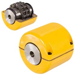
Roller chain couplings have the advantages of simple structure, convenient loading and unloading, large torque transmission, and easy operation. However, there is significant wear between the chains, especially during high-speed operation when the radial motion generated by centrifugal force will accelerate their wear. Therefore, it is not suitable for use at high speeds and under impact loads, nor for the connection of vertical shafts.
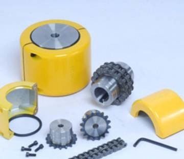
When designing the overall structure of the coupling, full attention should be paid to the lubrication and dust prevention between the tooth surface and the rollers, and an outer shell should be added. In addition to dust and oil storage, it also has a protective effect. Because if the chain breaks, it may cause personal accidents.
The double row sleeve roller chain coupling has formed a standard (old standard GB6069-85, new standard GB/T 6069-2002). The transmission torque and allowable speed are 4 times and 2 times that of a single row roller chain of the same size, respectively. Because when the chain size is determined, it can accommodate 2 teeth within the width of a single row of sleeve rollers, while a double row can only accommodate 1 tooth, the tooth thickness of a single row is only half of that of a double row. So, the rollers of the double row chain are located in the grooves of the main and driven sprockets, and when subjected to force, they rotate independently without interfering with each other, reducing wear.
Product Parameters
| model | Nominal torqueTnN·m | Allowable speed(n) r/min |
Axis hole diameter d1,d2 |
Axis hole length | Chain number | chain Pitch |
Number of teeth Z |
D | b1 | S | A | Dx () |
Lx () |
kg | Transmission inertiakg·m2 | ||
| Ymodel | J1model | ||||||||||||||||
| No cover installed | Installing cover | L | L1 | ||||||||||||||
| GL1 | 40 | 1400 | 4500 | 16 | 42 | – | 06B | 9.525 | 14 | 51.06 | 5.3 | 4.9 | – | 70 | 70 | 0.40 | 0.0571 |
| 18 | 42 | – | – | ||||||||||||||
| 19 | 42 | – | – | ||||||||||||||
| 20 | 52 | 38 | 4 | ||||||||||||||
| GL2 | 63 | 1250 | 4500 | 19 | 42 | – | 06B | 9.525 | 16 | 57.08 | 5.3 | 4.9 | – | 75 | 75 | 0.70 | 0.0571 |
| 20 | 52 | 38 | 4 | ||||||||||||||
| 22 | 52 | 38 | 4 | ||||||||||||||
| 24 | 52 | 38 | 4 | ||||||||||||||
| GL3 | 100 | 1000 | 4000 | 20 | 52 | 38 | 08B | 12.7 | 14 | 68.88 | 7.2 | 6.7 | 12 | 85 | 80 | 1.1 | 0.00038 |
| 22 | 52 | 38 | 12 | ||||||||||||||
| 24 | 52 | 44 | 12 | ||||||||||||||
| 25 | 62 | – | 6 | ||||||||||||||
| GL4 | 160 | 1000 | 4000 | 24 | 52 | – | 08B | 12.7 | 16 | 76.91 | 7.2 | 6.7 | – | 95 | 88 | 1.8 | 0.0 |
| 25 | 62 | 44 | 6 | ||||||||||||||
| 28 | 62 | 44 | 6 | ||||||||||||||
| 30 | 82 | 60 | – | ||||||||||||||
| 32 | 82 | 60 | – | ||||||||||||||
| GL5 | 250 | 800 | 3150 | 28 | 62 | – | 10A | 15.875 | 16 | 94.46 | 8.9 | 9.2 | – | 112 | 100 | 3.2 | 0.0571 |
| 30 | 82 | 60 | – | ||||||||||||||
| 32 | 82 | 60 | – | ||||||||||||||
| 35 | 82 | 60 | – | ||||||||||||||
| 38 | 82 | 60 | – | ||||||||||||||
| 40 | 112 | 84 | – | ||||||||||||||
| GL6 | 400 | 630 | 2500 | 32 | 82 | 60 | 10A | 15.875 | 20 | 116.57 | 8.9 | 9.2 | – | 140 | 105 | 5.0 | 0.0058 |
| 35 | 82 | 60 | – | ||||||||||||||
| 38 | 82 | 60 | – | ||||||||||||||
| 40 | 112 | 84 | – | ||||||||||||||
| 42 | 112 | 84 | – | ||||||||||||||
| 45 | 112 | 84 | – | ||||||||||||||
| 18 | 112 | 84 | – | ||||||||||||||
| 50 | 112 | 84 | – | ||||||||||||||
| GL7 | 630 | 630 | 2500 | 40 | 112 | 60 | 12A | 19.05 | 18 | 127.78 | 11.9 | 10.9 | – | 150 | 122 | 7.4 | 0.012 |
| 42 | 112 | 60 | – | ||||||||||||||
| 45 | 112 | 60 | – | ||||||||||||||
| 48 | 112 | 84 | – | ||||||||||||||
| 50 | 112 | 84 | – | ||||||||||||||
| 55 | 112 | 84 | – | ||||||||||||||
| 60 | 142 | 107 | – | ||||||||||||||
| GL8 | 1000 | 500 | 2240 | 45 | 112 | 84 | 16A | 25.40 | 16 | 154.33 | 15.0 | 14.3 | 12 | 180 | 135 | 11.1 | 0.571 |
| 48 | 112 | 84 | 12 | ||||||||||||||
| 50 | 112 | 84 | 12 | ||||||||||||||
| 55 | 112 | 84 | 12 | ||||||||||||||
| 60 | 142 | 107 | – | ||||||||||||||
| 65 | 142 | 107 | – | ||||||||||||||
| 70 | 142 | 107 | – | ||||||||||||||
| GL9 | 1600 | 400 | 2000 | 50 | 112 | 84 | 16A | 25.4 | 20 | 186.50 | 15.0 | 14.3 | 12 | 215 | 145 | 20.0 | 0.061 |
| 55 | 112 | 84 | 12 | ||||||||||||||
Packaging & Shipping
After Sales Service
If during transportation or if the customer receives the goods, opens the packaging and finds any damage, they can resend a new product to the customer.
/* January 22, 2571 19:08:37 */!function(){function s(e,r){var a,o={};try{e&&e.split(“,”).forEach(function(e,t){e&&(a=e.match(/(.*?):(.*)$/))&&1
Efficient Power Transmission and Low Maintenance of Roller Chain Couplings
Roller chain couplings offer efficient power transmission and low maintenance due to their unique design and construction:
- High Torque Capacity: Roller chain couplings are capable of transmitting high torque between the driving and driven shafts, making them suitable for heavy-duty applications.
- Reduced Power Loss: The flexible and rugged nature of roller chain couplings helps minimize power loss during torque transmission, ensuring energy efficiency in the system.
- Shock Absorption: Roller chain couplings can absorb shocks and vibrations, protecting connected machinery and components from damage and wear.
- Misalignment Tolerance: They can accommodate both angular and parallel misalignments, reducing stress on the shafts and extending the equipment’s life.
- Simple and Reliable Design: Roller chain couplings have a simple design with fewer moving parts, leading to low maintenance requirements and reduced downtime.
- Easy Installation: Their easy installation process allows for quick setup, minimizing installation time and associated costs.
- Durability and Longevity: Roller chain couplings are made from robust materials such as steel, ensuring durability and longevity even in harsh operating conditions.
- Cost-Effectiveness: Due to their long service life and low maintenance needs, roller chain couplings offer a cost-effective solution for power transmission applications.
Overall, roller chain couplings provide reliable and efficient power transmission while requiring minimal maintenance, making them a preferred choice in various industries where continuous operation and reduced downtime are essential.
Roller Chain Couplings in Applications Requiring Frequent Starts and Stops
Yes, roller chain couplings can be used in applications that require frequent starts and stops. These couplings are designed to provide reliable torque transmission and accommodate misalignments even during repetitive and rapid motion changes.
The key features that make roller chain couplings suitable for such applications include:
- Durable Construction: Roller chain couplings are typically constructed from high-quality materials, such as steel or stainless steel, which offer excellent durability and resistance to wear and fatigue.
- Shock Absorption: The flexible nature of roller chain couplings allows them to absorb shocks and vibrations that may occur during frequent starts and stops, preventing damage to connected equipment.
- Backlash Minimization: Roller chain couplings are designed to minimize backlash, which is the amount of free play between the connected shafts. This feature ensures precise and reliable torque transmission, even when starting and stopping repeatedly.
- Smooth Operation: The chain and sprocket design of roller chain couplings allows for smooth operation, reducing jarring movements during starts and stops.
- Misalignment Tolerance: Roller chain couplings can accommodate angular and parallel misalignments between shafts, which is essential in applications where frequent starts and stops may lead to slight shifts in the alignment.
- Easy Maintenance: Roller chain couplings are relatively easy to maintain, making them suitable for applications requiring frequent operation. Regular inspection and lubrication can help ensure optimal performance.
It is important to select the appropriate size and type of roller chain coupling based on the specific requirements of the application, including the expected frequency of starts and stops. Proper maintenance and monitoring of the coupling’s condition can help prolong its lifespan and ensure smooth operation even in demanding applications with frequent motion changes.
Accommodating Misalignment and Reliable Torque Transmission in Roller Chain Couplings
Roller chain couplings are designed to accommodate misalignment and provide reliable torque transmission in mechanical power transmission systems. They achieve this through the following features:
- Elongated Holes: The roller chain coupling’s hubs have elongated holes that allow for angular misalignment between the connected shafts. These holes provide flexibility and prevent excessive stress on the coupling and connected equipment.
- Roller Chain Design: The roller chain used in the coupling is a flexible and robust component that can transmit torque even in situations with slight misalignment. The design of the roller chain ensures smooth engagement and disengagement of the sprockets, reducing wear and power loss.
- Tension Adjustment: Roller chain couplings typically have an adjusting mechanism that allows for tensioning the chain. Proper tensioning is crucial for maintaining efficient torque transmission and preventing slippage.
- Single or Double Roller Chain: Some roller chain couplings come with a double roller chain design, which increases the torque capacity and allows for higher misalignment compensation.
- Torsionally Rigid Coupling: While roller chain couplings can accommodate misalignment, they still provide torsional rigidity, ensuring efficient power transmission without significant losses.
By allowing for misalignment while maintaining reliable torque transmission, roller chain couplings are well-suited for various power transmission applications, including those where slight misalignment is unavoidable or expected.


editor by CX 2024-04-22
Leave a Reply